Exoskeleton PCB & Control System
Designed a large-format integrated control PCB and distributed I/O board system for an upper-body exoskeleton research platform. The architecture splits centralized power and compute (Raspberry Pi, motor drivers, solar charging, OLED) from compact per-joint I/O modules — each driving BLDC motors and reading IMU sensors over an I2C bus — fabricated in KiCad and housed in custom 3D-printed ABS enclosures.
Control Electronics for a Research Exoskeleton
Upper-body exoskeletons require precise, coordinated motor control across multiple joints — shoulders, elbows, and wrists — with real-time feedback from inertial measurement units distributed along each limb segment. The control electronics must be compact enough to mount on the exoskeleton frame while handling the power demands of multiple brushless DC motors simultaneously.
This research project required designing integrated electronics that could drive multiple BLDC motors, process IMU data for real-time position feedback, and operate from a solar-charged battery system for extended autonomous use in field conditions. The system also required a debug/status display and graceful degradation behavior so motor faults don't cascade across the full joint network.
Control Board & I/O Board Specifications
Control Board Requirements
- Centralized control and power distribution for the full system
- Control-computer agnostic — designed around Raspberry Pi 4 but swappable
- Graceful degradation: individual joint faults must not cascade to other joints
- Ability to add or swap filtering components on-board
- Integrates sensory feedback (IMU data) into the control loop
- Wireless communication between compute module and joint-level I/O boards
I/O Board Requirements
- Drives up to 6 BLDC motors — one per joint location
- Compact form factor designed to mount at each joint
- Voltage and current monitoring per motor channel
- Clean digital I2C bus for communication and field replaceability
- Modular design allowing convenient repair and component replacement per joint
Control Board & Distributed I/O Architecture
Main Control PCB
Designed a large-format custom PCB in KiCad that serves as the central control hub for the exoskeleton. The board integrates:
- Multiple BLDC motor driver stages with current limiting
- Raspberry Pi 4 compute module header with full GPIO access
- OLED display for real-time system status and debug output
- Solar charging input with voltage regulation for extended autonomous operation
- Power distribution rails for motor drivers and logic-level components
- ENIG surface finish for reliability and consistent solderability
Distributed I/O Boards
Rather than running all motor wiring back to a central board, the architecture uses compact per-joint I/O modules. Each I/O board drives up to two BLDC motors bidirectionally with voltage and current monitoring, communicates over an I2C bus daisy-chained across joints, and is designed to mount directly at each joint location for short wire runs and easy field replacement.
8-IMU Sensor Array
Built a multi-sensor data acquisition system using 8 BNO085 IMUs connected to a Teensy 4.1 via custom UART drivers with SLIP protocol framing over RS485 transceivers. Sensor fusion produces stable quaternion orientation estimates per limb segment for PID feedback.
Interactive PCB Model
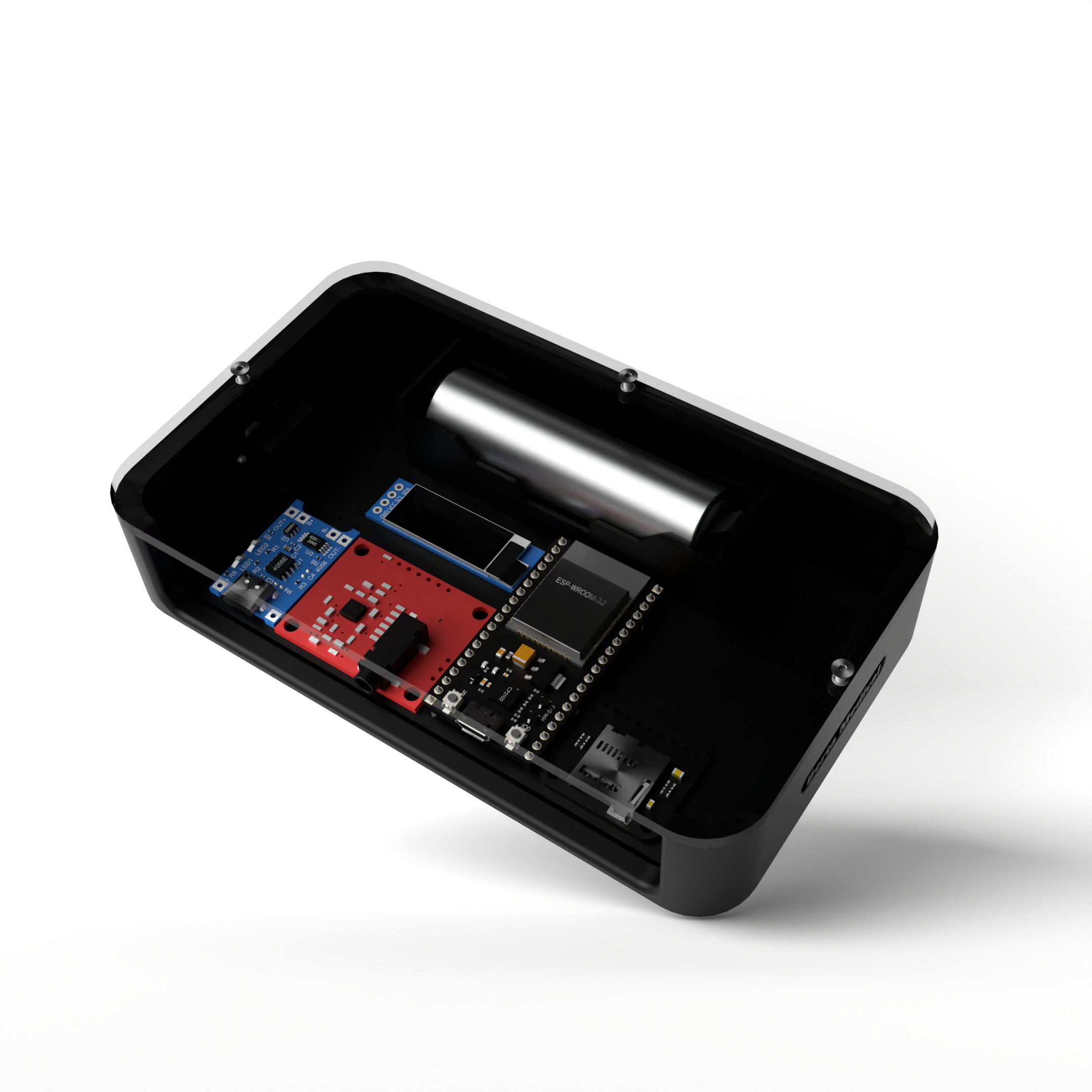
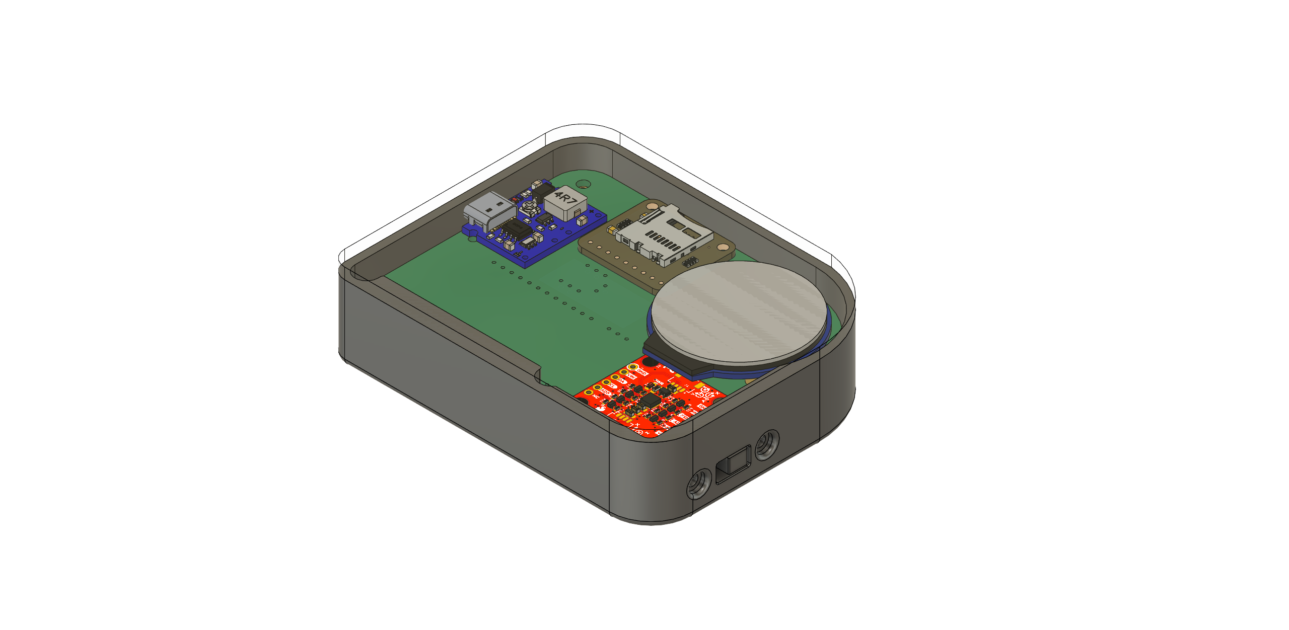
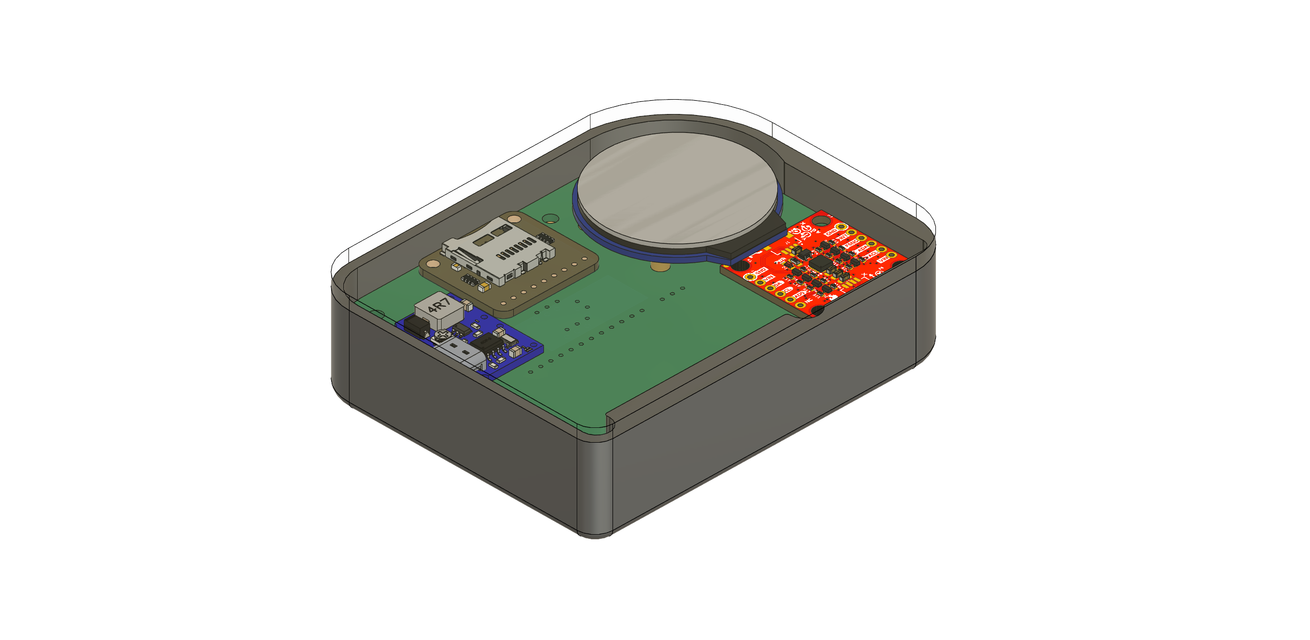
3D-Printed Housing & Hardware Integration
Custom ABS enclosures were designed in Fusion 360 and printed on a Bambu Lab P1S to protect the electronics and mount them to the exoskeleton frame. The enclosure design accounts for:
- Thermal dissipation from motor driver ICs — ventilation channels and thermal pad contact points
- Accessible debug ports and OLED display window for field use without full disassembly
- Secure PCB standoffs and fastener pockets to survive vibration from motor actuation
- Routing cutouts for motor phase wires and sensor harnesses at each joint
The I/O board enclosures are smaller and designed to clamp directly to the exoskeleton tubing at each joint location, keeping wire runs short and minimizing harness complexity.
Real-Time Motor Control & Sensor Fusion
Control software runs on the Raspberry Pi in Python, implementing PID control loops for each motor joint. IMU data from the 8-sensor BNO085 array feeds into the control loop to provide real-time position and orientation feedback, enabling smooth joint tracking and trajectory following.
The Teensy 4.1 handles low-level sensor communication — custom UART drivers for the BNO085 IMUs with SLIP protocol framing ensure reliable data delivery over the RS485 physical layer, which provides noise rejection over the longer cable runs required for distributed sensor placement across the exoskeleton frame.
Sensor fusion algorithms combine accelerometer, gyroscope, and magnetometer data from each BNO085 to produce stable quaternion orientation estimates per limb segment. These feed back to the Raspberry Pi PID controller over RS485.
The OLED display shows real-time motor states, battery voltage, solar charging status, and sensor health — enabling field debugging without a laptop.
Pre-Fabrication Design Decisions
- 24V to 5V regulation at ≥3A: Motor drivers demand significant current at high duty cycles; linear regulators were ruled out in favor of switching regulators to manage heat at the main board level.
- Heat management: Motor driver ICs sit on exposed copper pours with thermal via arrays connecting to the board's bottom copper layer; enclosure design includes corresponding thermal pad contact zones.
- Control-computer agnostic: The Raspberry Pi header pinout is standard 40-pin GPIO — future swaps to a Jetson or other SBC require only a carrier board adapter, not a full PCB revision.
- Graceful degradation: Each I/O board operates independently over the I2C bus; a fault on one joint's board does not lock up the bus or disable adjacent joints.
- ENIG finish: Selected for the control board for reliable and repeatable solderability across fine-pitch motor driver pads and the Raspberry Pi header.
Signal Verification & Position Tracking
Electrical Validation
- Power rail voltages verified under motor load conditions — no drooping beyond spec
- Motor driver waveforms captured and confirmed against expected PWM duty cycle profiles
- I2C bus integrity confirmed across full I/O board chain with logic analyzer
- RS485 BNO085 IMU data verified on each of the 8 sensor channels
Control System Validation
- PID position control loops tuned per joint and tested for step response overshoot and settling time
- Position and velocity tracking data logged and compared against commanded trajectories
- Graceful degradation confirmed — simulated I/O board fault isolated to one joint without disrupting other joints on the bus
Physical Integration
- Electronics package mounted and functionally tested on the exoskeleton frame in the Rowan research lab
- Full joint actuation sequence verified with real upper-body exoskeleton hardware
Lessons & Planned Improvements
The split architecture — centralized control board plus distributed I/O boards — proved the right call for a research platform. Adding or reconfiguring joints means swapping an I/O board rather than redesigning the main PCB.
Planned improvements:
- Expand I/O board motor channel count and update routing layout to accommodate additional joints as the exoskeleton grows
- Investigate upgrading from RS485/SLIP to a higher-bandwidth protocol as IMU count scales
- Tighter enclosure tolerances — the current ABS prints have adequate fit but a refined version would reduce assembly time and connector alignment effort
- Hardware-in-the-loop simulation setup for validating PID gains before mounting on the physical exoskeleton